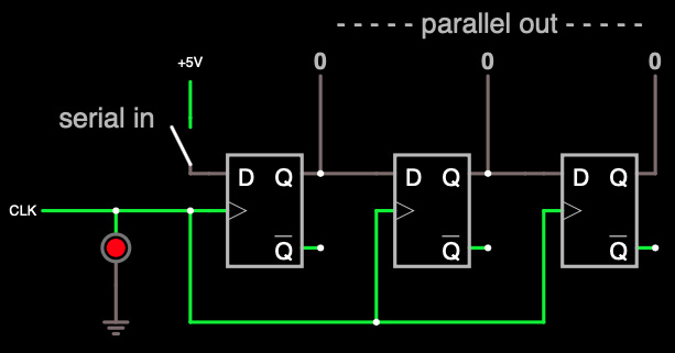
Build the circuit shown in the following screenshot.
This circuit is a 3-bit shift register (see Slide 300 from Lecture 16).
The “CLK” (under “Inputs and Sources / Add Clock”) simulates a stream of ones and zeros, such as is used to "clock" the circuits in a computer. The clock's default speed is 100 Hz, which can be adjusted by right clicking on it and changing "Frequncy", but it is easier to change the rate at which the simulation runs using the slide-pot labeled, “Simulation Speed.” Note that even at maximum simulation speed, the simulation runs much slower than real-time, as evidenced by value "t" (time) shown by default in the lower right-hand corner of the simulation. Thus events transpiring at 100 Hz appear to happen much slower.
Pressing the switch at "serial in" should cause the 1's and 0's at "parallel out" to change in a manner consistant with a shift register. Once you verify that the simulation works, select the menu command "File/Export as Link" in the circuit simulator, and cut-and-paste the link into Question 1 of the VLab2 report on CourseWeb.
In Question 2 of the VLab2 report, answer the following questions:
A. Explain the theoretical operation of the circuit, including the meaning "serial in" and "parallel out", with a detailed explanation of the behavior of the flip-flops.
B. Descripe the behavior of 1's and 0's with various activation patters using the switch.
C. Explain how this is a "state machine" because of the synchronous activation of the clocks.
D. What are the relative advantages of serial and parallel data in computers, and where might one find each?