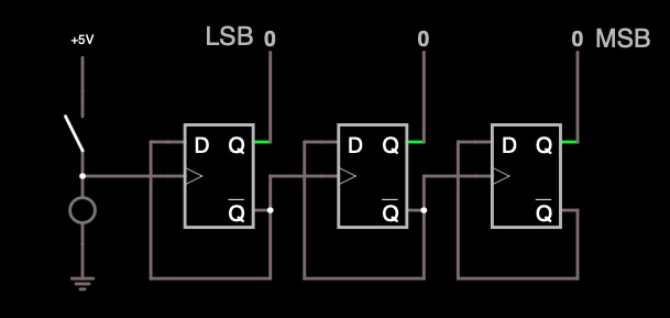
Build the circuit shown in the following screenshot.
Most of what you need to know to build it is covered in the first 3 Virtual Lab Videos. The +5V component is found in the Draw menu under “Inputs and Sources / Add Voltage Source (1-terminal)”. The circle under the switch is an LED. "LSB" (Least Significant Bit) and "MSB" (Most Significant Bit) aren’t buttons, they’re just labels (Output and Labels / Add Text).
Be sure to use Logic Outputs instead of Logic Inputs for the Boolean values at the top. If you use a “Logic Input” there, you will get a "singular matrix" error, because you will have connected 2 outputs together (A "Logic Input" serves as an output to the circuit it is connected to).
Tip: If the circuit response gets very sluggish, try saving it as text and reimporting it. It's written in Java as an applet running on your local computer, so should not be limited by internet bandwidth.
Once you verify that the simulation works, select the menu command "File/Export as Link" in the circuit simulator, and cut-and-paste the link into Question 1 of the VLab1 report on CourseWeb.
This circuit is a 3-bit ripple counter (see Slide 301 from Lecture 16). In Question 2 of the VLab1 report, answer the following questions:
A. Explain the theoretical operation of the circuit. Why is the LSB first and the MSB last?
B. Record the sequence of 3-bit numbers over at least 9 activations of the switch. Explain the sequence, including why it repeats.
C. The circuit in this lab is different from that on Slide 301. Explain how it is different and what effect this would have on its behavior as a counter.
D. What problem might arise as the number of bits in the counter (and flip-flops in the shift-register) gets much bigger than 3?